A tutorial about vertices manipulation using materials in Unreal Engine 4
Part 1: Transform position
Part 2: Scaling objects
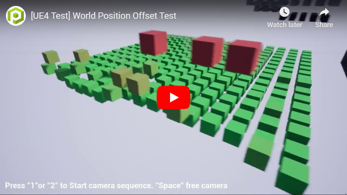
In the first part of this tutorial series we are going to show how to apply a vertex manipulation of specific sections of our model to simulate the transform of the location of part of our model.
The World Position Offset input allows for the vertices of a mesh to be manipulated in world space by the Material. This is useful for making objects move, change shape, rotate, and a variety of other effects.
With this tutorial we are going to learn how to modify the position of the vertices of a model using the information stored in a texture. We are going to apply a transform to the location of the vertices of a cube and change their relative height into the model.
Our first step is to prepare our model, more exactly the UV maps of the model. We can set multiple UV maps for the model.
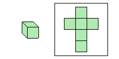
A UV map is the flat representation of the surface of a 3D model used to easily wrap textures. For example, an UV map for a 3d cube can be this:
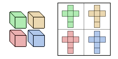
We want to make a 4-cube model and allocate the UV map of each cube in one section of the UV map of the model. So each time that we applied a change to that section all the vertices of that cube we will be affected.
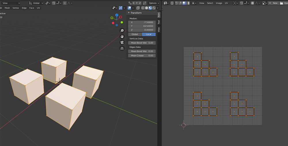
If we open our model into Blender, we can see this uvmap distribution using the UV editor view. As we can see, we have put the uvmap of each cube separated using a grid distribution.
Now we can start to design our texture. We are going to use the information stored in the color of each pixel to move the cube, more specifically the RGB value.
As we can have 3 values stored for one pixel and 3 axis in our world we can assign one axis for each color channel, so an increase of this channel value will be an increase of the value of this axis in the model for all the vertices contained in the section of the texture pixel.
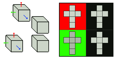
For example, using a pixel with a RGB value (255, 0, 0) we will modify only the X-axis position of that cube, with a RGB (0, 255, 0) we will modify their Y-axis position, and with a RGB (255, 255, 0) we can modify their X-axis and Y-axis at the same time.
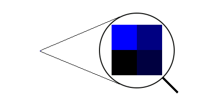
As we only have a 2 x 2 cube grid we only need a texture of 2 x 2 pixels for this model, each pixel will control one cube.
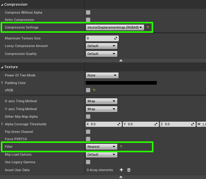
Now we can import the model and the texture into our Unreal Engine project.
We need to set the Compression Setting to VectorDisplacementMap and Filter to Nearest in the texture options.
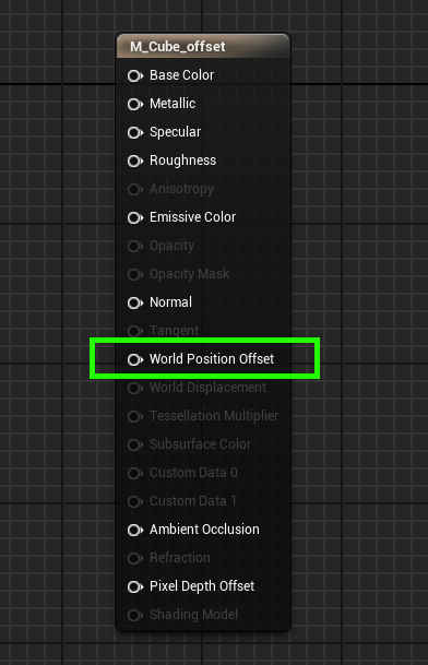
Now we can create a Material.
We can find the World Position Offset pin in the material node.
Now we can add a Texture Sample with the previous texture directly to the World Position Offset. We have our UV map in the first position of the UV map list so we need to take the TexCoord node with index 0.
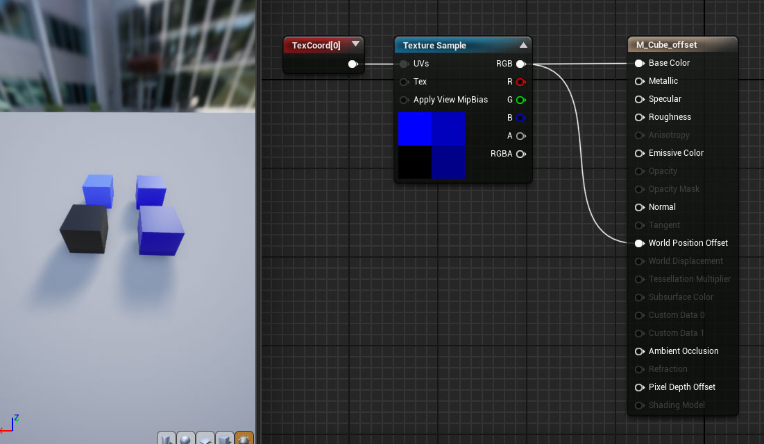
Now we have moved the cubes along the z-axis, but the offset has been of only of 1 unit (the value of the texture has a range from 0.0 to 1.0). So we can’t appreciate the change of position of the cubes, we need to scale the offset.
We can add a Multiply node before the World position Offset.
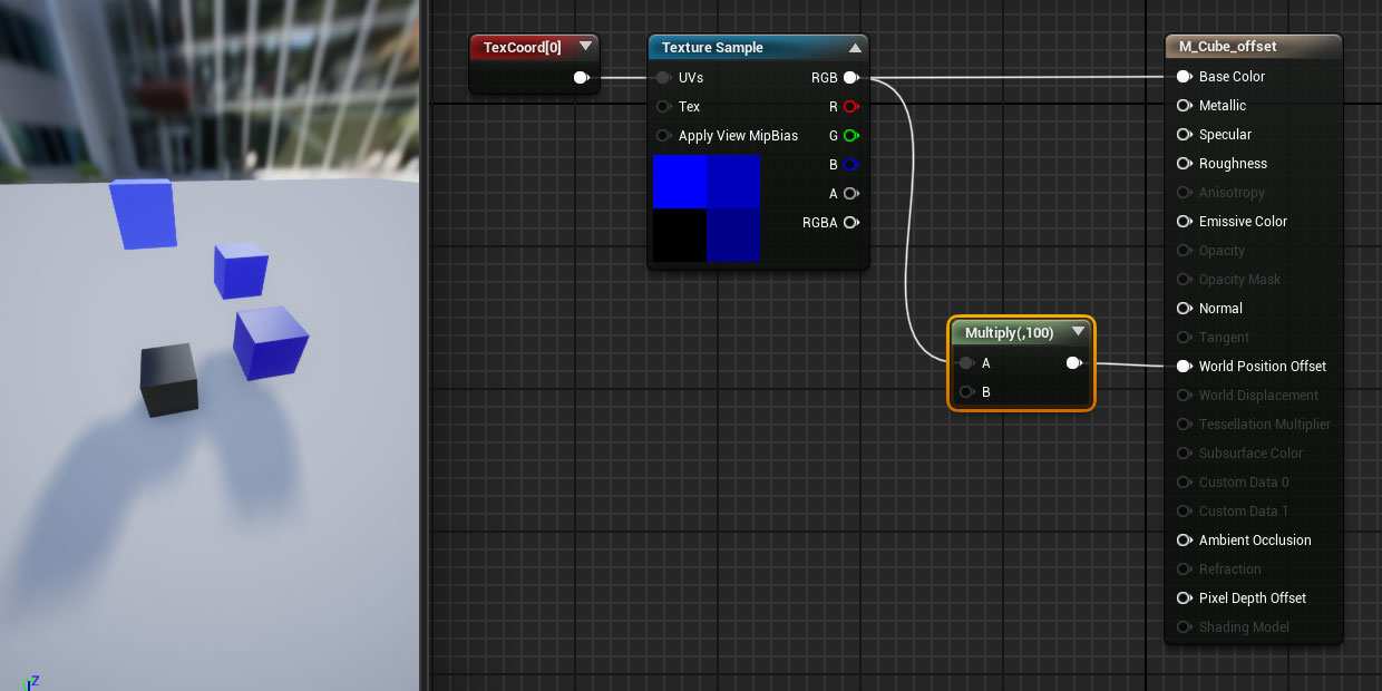
Now we can appreciate the displacement of the cubes.
Some issues
When using World Position Offset to expand your object beyond its original bounds, keep in mind that the renderer still uses those original bounds. This means that we may see culling and shadowing errors.
We can go into the properties of a mesh and set its Scale Bounds property to compensate, though this has a draw on performance and may lead to shadowing errors.
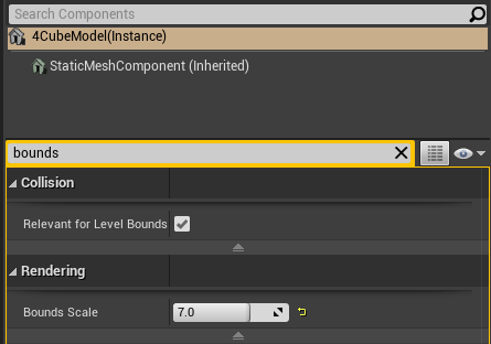
To find the exact value needed to scale the bounds of the object we can set the material model with the max value of the displacement of their vertices and enable the view of the object bounds in the preview viewport
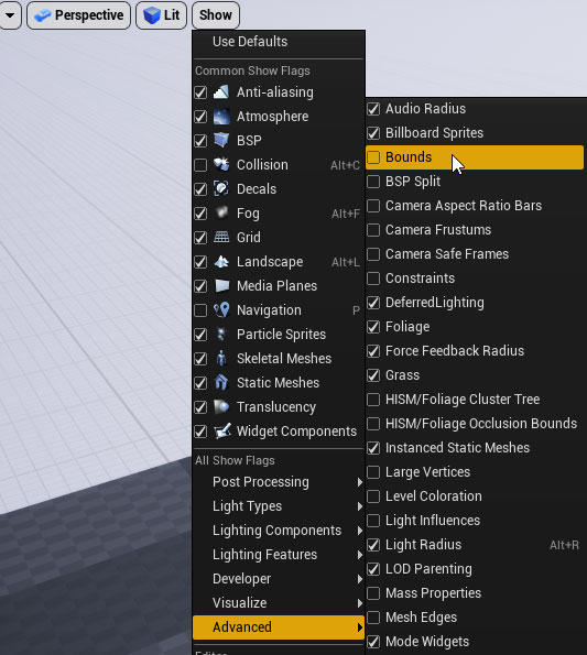
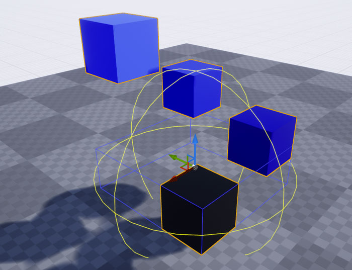
Now if we select the object we can see their bounds
To highlight the pixels out of the object bounds we can enable the option in the current viewport
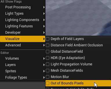
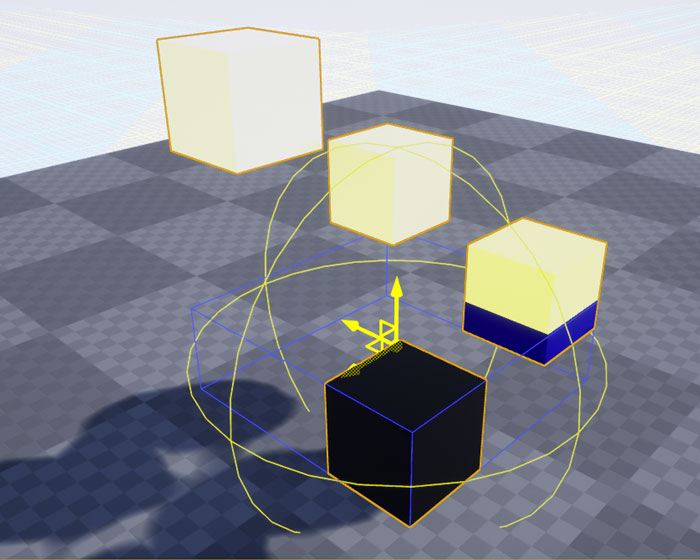
Now just we need to increase the Bounds scale value until the Out of bounds pixels disappear.
With this change we have fixed the culling problem of our model
Tutorial files
You may also like:
Support this blog!
For the past year we have been dedicating more of our time to the creation of tutorials, mainly about game development. If you think these posts have either helped or inspired you, please consider supporting this blog. Thank you so much for your contribution!